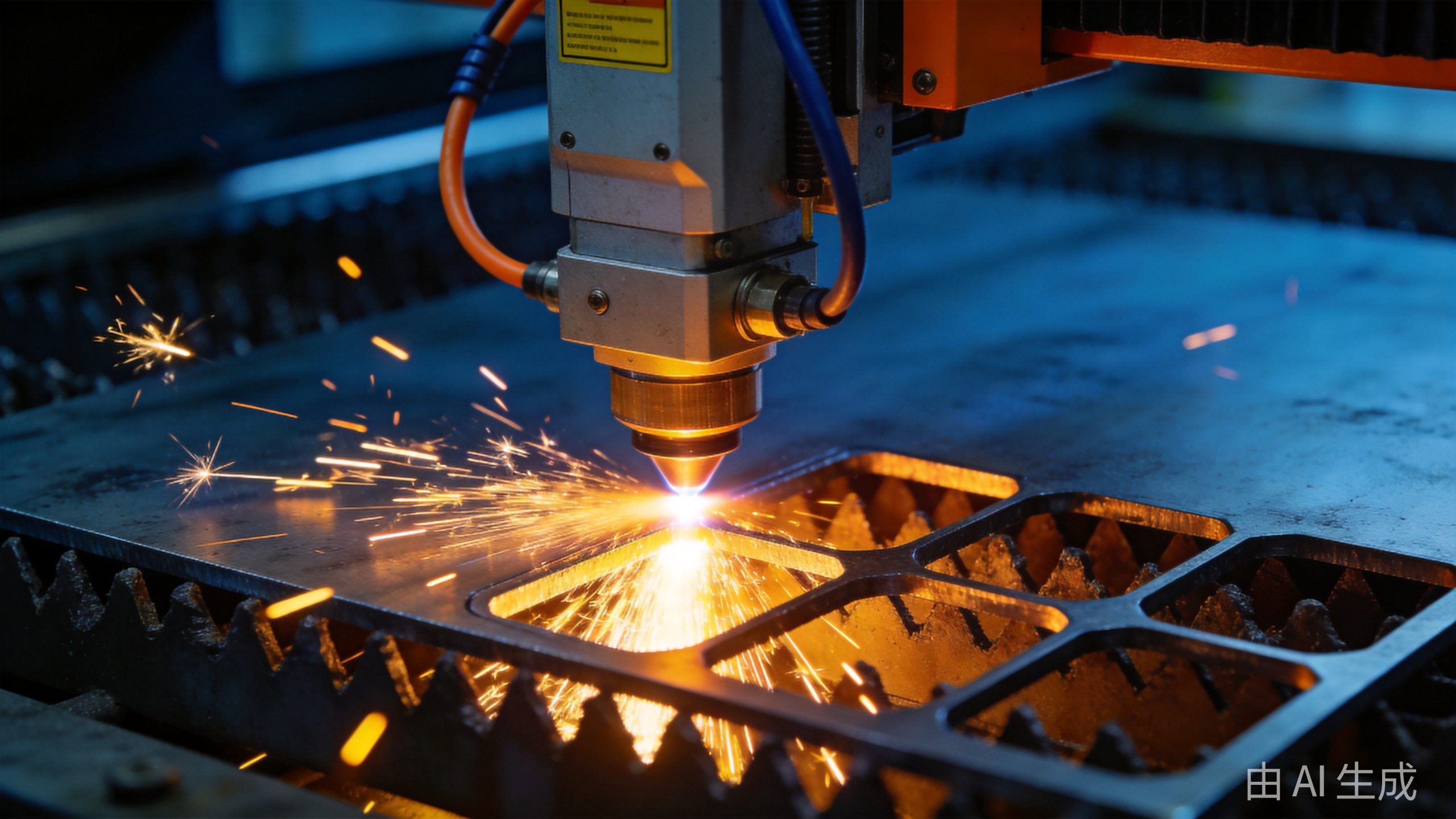
If you’ve ever wondered how a beam of light can slice through thick metal with precision measured in hundredths of a millimeter, you’re asking the right question. Fiber laser cutting machines have transformed metal fabrication, but the technology inside them is surprisingly complex.
In this guide, we break down exactly how a fiber laser cutting machine works — component by component, step by step. Whether you’re evaluating a purchase, training operators, or simply curious about the technology, you’ll come away with a clear understanding of the entire process.
Quick Overview: What Is a Fiber Laser Cutting Machine?
A fiber laser cutting machine uses a high-power fiber laser beam to melt, burn, or vaporize material — typically sheet metal — along a programmed path. The “fiber” in the name refers to the fiber optic cable that delivers the laser beam from the resonator to the cutting head.
Compared to CO2 lasers and plasma cutters, fiber lasers offer:
Learn more about the differences in our Fiber Laser vs CO2 Laser Cutting Machine Comparison.
Core Components of a Fiber Laser Cutting Machine
Before we trace the laser beam from generation to cut, let’s identify the key components involved.
1. Laser Resonator (Fiber Laser Source)
The resonator is the heart of the machine — where the laser beam is actually generated. In a fiber laser, the resonator consists of:
The result: a coherent, high-power laser beam at 1064 nm wavelength, delivered through a flexible fiber optic cable.
Power levels for industrial cutting machines typically range from 1 kW to 30 kW and beyond. Higher power = faster cutting and thicker maximum material thickness.
2. Fiber Optic Delivery Cable
Once generated, the laser beam travels through a fiber optic delivery cable — sometimes called the “laser light cable” — from the resonator to the cutting head.
This cable is not your ordinary data fiber. It’s a specialized double-clad fiber designed to carry high-power laser energy safely and efficiently:
Key advantages of fiber delivery:
3. Cutting Head
The cutting head is where the laser beam is focused and delivered to the workpiece. It’s a precision assembly containing:
4. Motion System (Gantry & Drive)
The motion system moves the cutting head across the workpiece following the programmed cut path. Key elements:
Cutting speeds can reach 20–40 m/min on thin sheet metal, with positioning accuracy of ±0.03 mm or better.
5. Worktable & Material Handling
6. CNC Control System
The Computer Numerical Control (CNC) system is the brain of the machine:
Modern CNC systems include features like:
7. Assist Gas System
Assist gas plays a crucial role in the cutting process — it’s not just “blowing away molten metal.” The gas:
Common assist gases:
Step-by-Step: How the Cutting Process Works
Now let’s walk through the entire process, from pressing “Start” to a finished cut part.
Step 1: Material Loading & Alignment
The operator places a sheet of metal on the worktable. For precision cuts, the sheet is aligned against reference pins or edges. On machines with pallet changers, this happens on the offline pallet while the machine is cutting on the other one.
Step 2: Program Loading
The operator selects the cutting program — a G-code file generated from a CAD drawing by nesting software. The program defines:
Step 3: Piercing
Before cutting along a path, the laser must first pierce through the material to create a starting hole. This is typically done with:
For thick materials, piercing can be the slowest part of the process. Advanced machines use techniques like modulation piercing or step piercing to speed it up while preventing spatter damage.
Step 4: The Cut
Once pierced, the cutting head moves along the programmed path. Here’s what happens at the focal point:
1. Absorption: The 1064 nm laser beam is absorbed by the metal surface, rapidly heating it.
2. Melting/Vaporization: The temperature rises above the metal’s melting point (and sometimes boiling point), creating a molten pool or vapor cavity.
3. Gas ejection: Assist gas blows through the nozzle, forcing the molten material down through the kerf and out the bottom of the sheet.
4. Motion: The cutting head moves continuously, creating a clean cut edge as it progresses.
The kerf (width of the cut) is typically 0.1–0.5 mm — much narrower than plasma or waterjet cutting.
Step 5: Cornering & Detail Features
When the cut path changes direction (corners, holes, contours), the machine automatically adjusts:
This is why high-quality CNC control and motion systems matter — the difference between a sharp corner and a rounded one comes down to how well the machine coordinates motion and laser power.
Step 6: Part Separation & Unloading
After the cut is complete, the finished parts fall through the slatted table (for small parts) or remain on the table for manual removal. On pallet changer machines, the pallets swap and the next sheet is ready to cut within seconds.
Key Parameters That Affect Cut Quality
Understanding how the machine works helps you optimize these critical parameters:
Laser Power
Higher power = faster cutting and thicker capacity. But more power isn’t always better — too much power on thin material causes excessive heat input and poor edge quality.
Cutting Speed
Speed must be matched to power and material thickness. Too fast = incomplete penetration. Too slow = excessive heat, wide kerf, and wasted time.
Focus Position
The focal point’s vertical position relative to the material surface dramatically affects cut quality:
Gas Type & Pressure
Beam Quality (BPP)
Beam Parameter Product (BPP) measures how tightly a laser can be focused. Lower BPP = better beam quality = finer cuts. Fiber lasers typically have BPP values of 0.3–2 mm·mrad, far better than CO2 lasers of equivalent power.
Common Cutting Modes
Fiber laser cutting machines operate in several modes depending on the application:
1. Fusion Cutting
2. Flame Cutting (Oxygen Cutting)
3. Sublimation Cutting (Vaporization Cutting)
4. Drilling & Piercing
Safety Systems
Fiber laser cutting machines include multiple safety layers:
Maintenance Requirements
One of the biggest advantages of fiber lasers over CO2 lasers is reduced maintenance. Here’s what’s needed:
| Component | Maintenance Frequency | What’s Done |
|---|---|---|
| Nozzle | Daily | Clean or replace if damaged |
| Protective window | Daily–Weekly | Clean or replace if contaminated |
| Focus lens | Monthly–Quarterly | Inspect and clean |
| Fiber cable | Annually | Inspect for damage |
| Guide rails & drives | Weekly | Lubrication and inspection |
| Filter system | Per usage | Replace fume filters when full |
| Laser source | 50,000+ hr life | No routine maintenance needed |
The fiber laser source itself has a typical lifetime of 50,000–100,000 hours — essentially the life of the machine — with no scheduled maintenance required.
How Fiber Laser Cutting Differs from Other Technologies
| Technology | How It Works | Best For |
|---|---|---|
| Fiber Laser | Focused laser beam melts/vaporizes metal; assist gas blows away molten material | Thin to medium sheet metal (0.5–25 mm steel), high precision, high volume |
| CO2 Laser | Gas laser (CO2 mixture) at 10.6 µm wavelength, delivered via mirrors | Thicker materials, non-metals, lower capital cost for high power |
| Plasma Cutting | Ionized gas arc melts and blows away metal | Thick metal (up to 50+ mm), lower precision, faster on thick material |
| Waterjet Cutting | High-pressure water + abrasive erodes material | Virtually any material, no heat-affected zone, but slower |
For a detailed breakdown, see our Fiber Laser vs Plasma Cutting Comparison.
Conclusion
A fiber laser cutting machine works by generating a high-power laser beam in a fiber-optic resonator, delivering it through a flexible fiber cable to a precision cutting head, and focusing it onto the workpiece to melt, burn, or vaporize material along a CNC-controlled path. Assist gas removes molten material and protects the optics, while the motion system ensures accurate, repeatable cuts.
The key advantages — high speed, excellent precision, low operating cost, and minimal maintenance — explain why fiber lasers have become the dominant technology in sheet metal fabrication.
If you’re considering a fiber laser cutting machine for your business, check out our Fiber Laser Cutting Machine Buyer’s Guide or explore Transon Laser’s fiber laser product lineup. For questions about specific applications or pricing, contact our team — we’re happy to help.
Further Reading: